
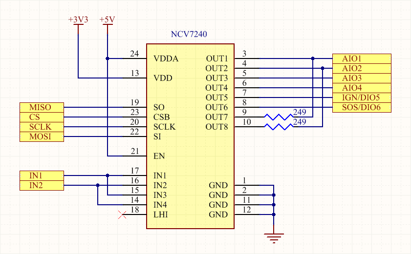
There is an 8 channel relay output driver on the internal SPI interface, with the first 6 channels that share the same pin with digital and analog inputs of the Main connector, and the last 2 channels that can enable 4-20 mA input interface on the first 2 analog inputs. Output channels can also be configured to be controlled by digital pins, with support for PWM mode (IN1 for odd channels, IN2 for even channels).
Here below the simplified schematics:
Here is an example Arduino sketch that configures the driver and toggles AIO1 and AIO2 outputs using GPIO pins:
#include <SPI.h>

void setup() {
  // Open and wait serial terminal
  Serial.begin(115200);
  while (!Serial);
  // Enable 5V regulator
  pinMode(PIN_C_5V_ENABLE, OUTPUT);
  digitalWrite(PIN_C_5V_ENABLE, HIGH);
  delay(100);
  // Configure chip-select pins
  pinMode(PIN_C_OUT_CS, OUTPUT);
  pinMode(PIN_C_ACC_CS, OUTPUT);
  digitalWrite(PIN_C_OUT_CS, HIGH);
  digitalWrite(PIN_C_ACC_CS, HIGH);
  // Set control pins
  pinMode(PIN_C_OUT_1, OUTPUT);
  digitalWrite(PIN_C_OUT_1, LOW);
  pinMode(PIN_C_OUT_2, OUTPUT);
  digitalWrite(PIN_C_OUT_2, LOW);
  // Initialize SPI
  SPI.begin();
  SPI.setDataMode(SPI_MODE1);
  SPI.setClockDivider(SPI_CLOCK_DIV64);
  // Configure Channels 1-2 as Input (pin driven)
  digitalWrite(PIN_C_OUT_CS, LOW);
  SPI.transfer(0x00);
  SPI.transfer(0x05);
  digitalWrite(PIN_C_OUT_CS, HIGH);
  SPI.end();
}

void loop() {
  // Toggle outputs
  digitalWrite(PIN_C_OUT_1, HIGH);
  delay(500);
  digitalWrite(PIN_C_OUT_2, HIGH);
  delay(500);
  digitalWrite(PIN_C_OUT_1, LOW);
  delay(500);
  digitalWrite(PIN_C_OUT_2, LOW);
  delay(500);
}
The same example with Zerynth:
from fortebit.polaris import polaris
from fortebit.polaris import ioexpander

polaris.init()
iox = ioexpander.IOExpander()

pinMode(polaris.main.PIN_IOEXP_IN1, OUTPUT)
pinMode(polaris.main.PIN_IOEXP_IN2, OUTPUT)

iox.setAllChannels(iox.CH_STANDBY)
iox.setAllChannels([iox.CH_INPUT, iox.CH_INPUT])

while True:
    digitalWrite(polaris.main.PIN_IOEXP_IN1, HIGH)
    sleep(500)
    digitalWrite(polaris.main.PIN_IOEXP_IN2, HIGH)
    sleep(500)
    digitalWrite(polaris.main.PIN_IOEXP_IN1, LOW)
    sleep(500)
    digitalWrite(polaris.main.PIN_IOEXP_IN2, LOW)
    sleep(500)