

The outer headers J1 and J2 are the mikroBUS™ interface connectors, providing selectable 3.3V/5V power input to the module and voltage translated digital I/O lines, including: UART receive/transmit lines and control pins.
The header J3 provides configurable I/O expansion lines (inputs with weak internal pull-up by default), powered at the internal logic voltage VDD.
The header J4 contains the main analog signals, such as microphone signals and amplified DAC outputs, which are also available on the internal right angle connectors J5 and J6.
The module can also be operated through the programming connector J7 alone, by using the QuickUSB Adapter Cable.
Pin assignment
| Group | Name | Number | Pin | Type | Description | |
| ● | MIKROBUS | J1 | 1 | – | – | (Not connected) |
| 2 | RST | I | Active low asynchronous reset (internal pull-up) | |||
| 3-6 | – | – | (Not connected) | |||
| 7 | 3V3 | I | 3.3V DC power input | |||
| 8 | GND | – | Ground | |||
| J2 | 1 | XM | I | Boot select (internal pull-down) | ||
| 2 | DE | O | (Reserved) | |||
| 3 | TX | O | Serial Data Transmit | |||
| 4 | RX | I | Serial Data Receive | |||
| 5-6 | – | – | (Not connected) | |||
| 7 | 5V | I | 5.0V DC power input | |||
| 8 | GND | – | Ground | |||
| ● | GPIO | J3 | 1 | IO1 | I/O | General purpose I/O (VDD logic levels) |
| 2 | IO2 | I/O | General purpose I/O (VDD logic levels) | |||
| 3 | IO3 | I/O | General purpose I/O (VDD logic levels) | |||
| 4 | IO4 | I/O | General purpose I/O (VDD logic levels) | |||
| 5 | IO5 | I/O | General purpose I/O (VDD logic levels) | |||
| 6 | IO6 | I/O | General purpose I/O (VDD logic levels) | |||
| ● | AUDIO | J4 | 1 | SP+ | O | Differential audio output (can directly drive 8Ω speaker) |
| 2 | SP- | O | ||||
| 3 | VM | O | Microphone power (to support custom microphones) | |||
| 4 | MIC | I | Microphone audio input | |||
| 5 | RET | – | Microphone return (analog ground) | |||
| 6 | VDD | O | Internal logic voltage (for reference only) | |||
| ● | CABLES | J5 | 1 | SP- | O | Differential audio output (can directly drive 8Ω speaker) |
| 3 | SP+ | O | ||||
| 2 | – | – | (Not connected) | |||
| J6 | 1 | MIC | I | Microphone audio input | ||
| 2 | RET | – | Microphone return (analog ground) | |||
| ● | ADAPTER | J7 | 1 | RX_P | O | Programming cable serial data receive |
| 2 | RTS_P | I | Programming cable request to send (reset/boot control) | |||
| 3 | GND | – | Programming cable ground | |||
| 4 | 5V_P | I | Programming cable 5V DC power output | |||
| 5 | TX_P | I | Programming cable serial data transmit | |||
| 6 | CTS_P | O | Programming cable clear to send (tied to ground) | |||
Note: The General Purpose I/O lines (J3.1-6) are at nominal 3.0VDC level. Do not connect higher voltages directly to these pins!
Settings and indicators
| Group | Name | Type | Description | |
| ● | MISC | PWR SEL | 3-Way Jumper
(SMD 0603) |
Select power input and voltage level between +3.3V and +5V with a zero Ohm resistor or solder bridge |
| D1 | LED | Red light indicator, normally ON when the board is powered, briefly blinking on serial data received | ||
| D2 | LED | Green light indicator, turns ON when the module is listening to its audio input | ||
| R4 | Resistor
(SMD 0603) |
Microphone gain resistor, default is 1.2kΩ | ||
Physical dimensions


| Symbol | Parameter | Units (mm / Inches) | |
| W | Width | 25.4 | 1.000 |
| L | Length | 56.4 | 2.220 |
| H1 | Height (without outer strips J1-J4) | 9.5 | 0.375 |
| H2 | Height (with outer strips J1-J4) | 17.0 | 0.670 |
| E1 | Connector pitch and pin spacing (of outer strips J1-J4) | 2.54 | 0.100 |
| E2 | Connector pitch (of inner connectors J5-J7) | 2.00 | 0.079 |
| A | Headers horizontal spacing | 22.86 | 0.900 |
| B | Headers vertical spacing | 20.32 | 0.800 |
| C | Header vertical offset | 3.81 | 0.150 |
| D | Header horizontal offset | 1.27 | 0.050 |
Recommended Operating Conditions
| Symbol | Parameter | Min | Typ | Max | Unit |
| 5V | DC Power Input (Host) = VSEL | 3.15 | 5.0 | 5.5 | V |
| 3V3 | 3.15 | 3.3 | 5.5 | V | |
| 5V_P | DC Power Input (Programming cable) | 4.0 | 5.0 | 5.5 | V |
| Ta | Ambient Operating Temperature Range | 0 | 25 | 70 | °C |
Power Supply Requirements
| Symbol | Parameter | Min | Typ | Max | Unit |
| ISLEEP | Sleep current (VSEL = 5.0V) | 6 | mA | ||
| IOPER | Operating current (VSEL = 5.0V) | 25 | 35 | mA | |
| IAUDIO | Audio playback current (with 8Ω speaker) | 175 | 250 | mA (RMS) | |
| ITOT | Total current consumption (excluding I/O) | 25 | 285 | mA (RMS) | |
| IPEAK | Peak supply current (excluding I/O) | 400 | mA |
Electrical Characteristics
These are applicable to pins RX, TX_P.
| Symbol | Parameter | Min | Typ | Max | Unit |
| VIH | Input High Voltage | 2.1 | 5.5 | V | |
| VIL | Input Low Voltage | 0.0 | 0.9 | V | |
| IIL | Input Leakage Current (0 < VI < 5.5V) | -65 | µA |
These are applicable to pins TX, DE.
| Symbol | Parameter | Min | Typ | Max | Unit |
| VOH | Output High Voltage (IOH = -0.3 mA, VSEL = 3.3V) | 2.6 | 3.3 | V | |
| Output High Voltage (IOH = -0.3 mA, VSEL = 5.0V) | 4.3 | 5.0 | V | ||
| VOL | Output Low Voltage (IOL = 5 mA) | 0.0 | 0.2 | V |
These are applicable to pin XM.
| Symbol | Parameter | Min | Typ | Max | Unit |
| VIH | Input High Voltage | 1.4 | (0.8) | 5.5 | V |
| VIL | Input Low Voltage | 0.0 | (0.7) | 0.5 | V |
| IIN | Input Current (0 < VI < 3.3V) | 0 | 0.2 | 0.4 | mA |
| Input Current (0 < VI < 5.5V) | 0 | 0.5 | 0.7 | mA |
These are applicable to pin RST.
| Symbol | Parameter | Min | Typ | Max | Unit |
| VIH | Input High Voltage | 2.1 | 5.5 | V | |
| VIL | Input Low Voltage | 0.0 | 0.6 | V | |
| IIL | Input Leakage Current (0 < VI < 5.5V) | -85 | µA |
These are applicable to pin RX_P.
| Symbol | Parameter | Min | Typ | Max | Unit |
| VOH | Output High Voltage (IOH = -5 mA) | 2.4 | 3.0 | V | |
| VOL | Output Low Voltage (IOL = 8 mA) | 0.0 | 0.6 | V |
These are applicable to pins IO1 – IO6.
| Symbol | Parameter | Min | Typ | Max | Unit | |
| VIH | Input High Voltage | 2.4 | 3.0 | 3.3 | V | |
| VIL | Input Low Voltage | -0.1 | 0.0 | 0.75 | V | |
| IIL | Input Leakage Current (0 < VI < 3V, Hi-Z Input) | <1 | 10 | µA | ||
| RPU | Pull-up Resistance | Strong | 10 | kΩ | ||
| Weak | 200 | kΩ | ||||
| VOH | Output High Voltage (IOH = -5 mA) | 2.4 | 3.0 | V | ||
| VOL | Output Low Voltage (IOL = 8 mA) | 0.0 | 0.6 | V | ||
Serial Interface
The EasyVR 3 communicates via an asynchronous serial interface (commonly known as UART interface), with the following features:
- Baud Rate: 9600 (default), 19200, 38700, 57600, 115200
- Frame: 8 Data bits, No parity, 1 Stop bit
The receiver input data line is RX, while the transmitter output data line is TX. No handshake lines are used.
Example of a serial data frame representing character “A” (decimal 65 or hexadecimal 41):
| VCC | ||||||||||||
| Idle | Start | 1 | 0 | 0 | 0 | 0 | 0 | 1 | 0 | Stop | Idle | |
| 0V |
See also chapter Communication Protocol later on this manual for communication details.
Microphone
The microphone provided with the EasyVR 3 module is an omnidirectional electret condenser microphone (Horn EM9745P-382):
- Sensitivity -38dB (0dB=1V/Pa @1KHz)
- Load Impedance 2.2K
- Operating Voltage 3V
- Almost flat frequency response in the range 100Hz – 20kHz
The microphone circuit is optimized for use at ARMS_LENGTH (default, about 60cm) or FAR_MIC distance settings.
If you use a microphone with different specifications the recognition accuracy may be adversely affected. Differences in rated load impedance and sensitivity can be compensated to a certain extent by changing the microphone gain. This can be done in several ways:
- Replacing the internal gain resistor R4 (1.2kΩ)
- Adding an external resistor Rx going in parallel with R4 (it can only reduce gain, useful for HEADSET distance settings)
- Removing the internal resistor R4 and using only the external resistor Rx

Microphone circuit
Modifying gain resistance
You can calculate the overall microphone gain resistance using the formula below:
Rs is the optimal microphone gain resistance
I is the impedance rating of the microphone
G is the desired overall system gain, defined as follows:
- If the module is configured for headset microphone distance (typically a few centimeters from the user’s mouth), then the overall system gain should be -49 dB (0dB=1v/Pa@1KHz);
- If the module is configured for arms_length microphone distance (typically 60-90 cm from the user’s mouth – this is the default setting of EasyVR), then the overall system gain should be -44 dB;
- If the module is configured for far_mic microphone distance (up to about 3 meters from the user’s mouth), then the overall system gain should be -43 dB.
S is the sensitivity rating of the microphone you want to use, and it is specified in –dB in the microphone’s specification.
Examples
- The optimal gain resistance for the bundled microphone at arms_length distance is:
Use the closest standard 5% resistor to Rs. In this example, it would be 1.1 kΩ. The EasyVR uses a 1.2 kΩ resistor to allow use of “FAR” settings without replacing the internal resistor.
Sometimes you might also need to compensate some gain loss for a voltage lower than the microphone ratings (using a larger resistor value sets a higher input gain).
- The gain resistance for the bundled microphone at HEADSET distance would be:
In this case you may just add an external 1.2 kΩ resistor to get a gain resistance of 600 Ω (close enough).
Positioning guidelines
Please note that improper acoustic positioning of the microphone will reduce recognition accuracy. Many mechanical arrangements are possible for the microphone element, and some will work better than others. When mounting the microphone in the final device, keep in mind the following guidelines:
1. Flush Mounting – The microphone element should be positioned as close to the mounting surface as possible and should be fully seated in the plastic housing. There must be no airspace between the microphone element and the housing. Having such airspace can lead to acoustic resonance, which can reduce recognition accuracy.

2. No Obstructions, Large Hole – The area in front of the microphone element must be kept clear of obstructions to avoid interference with recognition. The diameter of the hole in the housing in front of the microphone should be at least 5 mm. Any necessary plastic surface in front of the microphone should be as thin as possible, being no more than 0.7 mm, if possible.

3. Insulation – The microphone should be acoustically isolated from the housing if possible. This can be accomplished by surrounding the microphone element with a spongy material such as rubber or foam. The provided microphone has this kind of insulating foam. The purpose is to prevent auditory noises produced by handling or jarring the device from being “picked up” by the microphone. Such extraneous noises can reduce recognition accuracy.

4. Distance – If the microphone is moved from 15 cm to 30 cm from the speaker’s mouth, the signal power decreases by a factor of four. The difference between a loud and a soft voice can also be more than a factor of four. Although the internal preamplifier of the EasyVR compensates for a wide dynamic range of input signal strength, if its range is exceeded, the user application can provide feedback to the speaker about the voice volume (see appendix Error codes).
Audio Output
The EasyVR 3 audio output interface is capable of directly driving an 8Ω speaker. It can also be connected to an external audio amplifier to drive lower impedance loudspeakers.
Note: Connecting speakers with lower impedance directly to the module may permanently damage the EasyVR audio output or the whole module.

It is possible to connect higher impedance loads such as headphones, provided that you scale down the output power according to the speaker ratings, for example using a series resistor. The exact resistor value depends on the headphone sensitivity and the desired output volume (usually in the order of 1-10kΩ).
Note: Connecting headphone speakers directly to the EasyVR audio output may damage your hearing.
General Purpose I/O
Since the EasyVR communication interface takes two pins of the host controller, a few spare I/O pins are provided, which can be controlled with the communication protocol, to get those pins back for basic tasks, such as lighting an LED or reading a switch.
The six I/O pins IO1–IO6 are connected directly to the embedded microcontroller on the EasyVR module, so they are referenced to the internal 3.0V regulated power supply VDD. If you need to interface to circuits using a different supply, there are a number of solutions you can adopt. Some of these are outlined below (here IOn indicates any one of the six I/O pins of the EasyVR).
Use a pin as an output
All the I/O pins are inputs with weak internal pull-up after power on. You must explicitly configure a pin before you can use it as an output (see the example code Use general purpose I/O pins).

I/O pin directly driving a low-current LED

I/O pin connected to high impedance 5V circuit (such as MCU input pin)

I/O pin switching a load on a high voltage line using a 12V relay
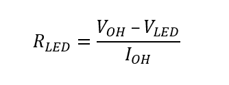
The exact components values in these circuits may vary. You need to calculate required values for your application and choice of components. For example, resistor value for the LED circuit can be calculated approximately as:
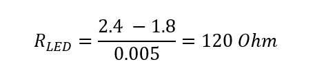
Where VLED is the LED forward voltage, as reported on the LED datasheet, at the driving current IOH (see section Electrical Characteristics). Let’s assume a typical low-current LED has a VF=1.8V at 5mA, the resistor value is:
Now stay on the safe side and choose a slightly larger resistor, such as 150Ω.
If you want to drive higher current LEDs, you need a circuit like the second one, where you put the LED between the output resistor and the collector of the NPN transistor.
Use a pin as an input
All the I/O pins are inputs with weak internal pull-up after power on or reset. You may also configure the pin to have a strong pull-up or no pull-up at all (see the example code Use general purpose I/O pins).

I/O pin connected to a switch (or switching sensor)

I/O pin connected 5V source (such as MCU output pin)

I/O pin with isolated input (for safety circuits)
All these circuits assume the EasyVR pin has been configured with an internal pull-up (passive components value can be adjusted to account for weak or strong pull-up).
Disabling the internal pull-up could be used to put the pin in high-impedance state, for example to simulate a tri-state or open-drain output port.
Again, you should refer to the manufacturer’s datasheet when interfacing any external components and to calculate required resistors values or other passive components.
Flash Update
The EasyVR module includes a boot loader that allows to update the firmware and to download new sound tables or custom grammars to the on-board memory.
The boot mode is activated by keeping the XM signal to a high logical level at power on or reset. This can be easily done with a jumper (or switch) taking the signal to a suitable pull-up resistor.
To download a firmware update, a sound table or a custom grammar to the EasyVR, power on the module with the jumper closed. For normal operation, just leave the jumper open. Do not change the jumper position while the module is already powered on. It is safe to change XM level while the module is reset (RST low).

Boot mode selection circuit
To learn how to download new sound tables or custom grammars to your EasyVR 3 module, have a look at the section Using Custom Data.