Assembly notes
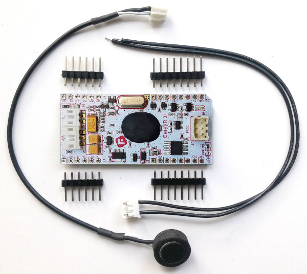
The EasyVR 3 is provided with separate standard 2.54mm-pitch male headers that can be used to connect the module to a breadboard, prototyping board, custom boards or carrier boards like the EasyVR Shield 3.
When male headers are necessary, make sure they are well soldered on the module in order to prevent electrical issues.
Some practical guides to hand soldering:

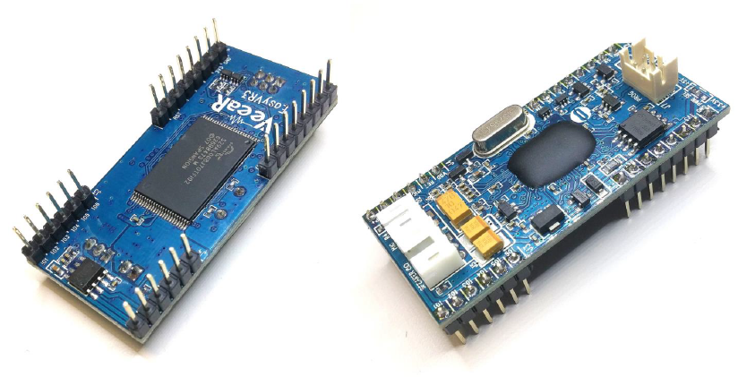
When assembling the module, especially in preparation for the EasyVR Shield 3, make sure you insert male headers from the bottom side and solder them on the top side, and that all the headers are straight and vertical for a smooth insertion on the carrier board.
The end result should be similar to the following pictures:

EasyVR 3 as a Development Board
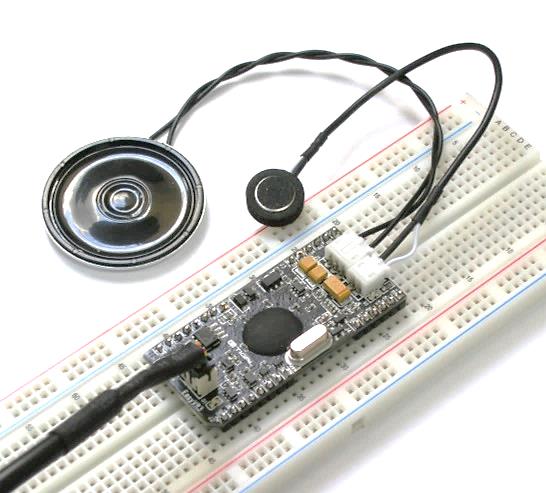
The EasyVR 3 module has been designed to allow use as a standalone development board when combined with a USB-Serial adapter.
The QuickUSB adapter cable can be used to program voice commands and sound outputs directly to an EasyVR 3 module and quickly test its functions from your PC.
Just connect the microphone and an 8Ω speaker to the module, plug-in the adapter cable and you are ready to go.
The EasyVR 3 boot mode is managed automatically through the serial handshake lines and you don’t need to set any jumper.

Getting started
1. Connect the microphone to the 2-way socket MIC (J6)
2. Connect an 8Ω speaker to the 3-way socket SPEAKER (J5)
3. Connect a QuickUSB cable to the 3×2 pins socket (J7)
4. Plug the USB end of the adapter cable to your PC.
The first time it may take some time to install the required drivers (see Software Setup)
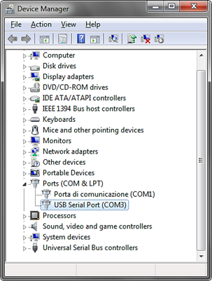
5. If your installation is successful you will see a new virtual COM port in your Device Manager:

(The actual COM port number may vary)
6. Now start the EasyVR Commander software
7. Choose your COM Port and click connect
8. Then enjoy your EasyVR!
Serial Adapter Interface
Connector J7 is a 6-pin socket specifically designed for the QuickUSB serial adapter cable, but another adapter may also be connected to this port, as long as it uses the same connector type, pin assignment and electrical specifications.
| Pin | Name | Type | Notes |
| 1 | RX_P | I | Adapter should have TTL/LVTTL compatible inputs (VIH = 2.0V) |
| 2 | RTS_P | O | Adapter outputs can have 3.3V or 5V levels RTS handshake is required for automatic reset and boot mode control |
| 3 | GND | – | Common ground |
| 4 | 5V_P | O | Adapter should provide a 5V DC power output for the module (see Recommended Operating Conditions and Power Supply Requirements) |
| 5 | TX_P | O | Adapter outputs can have 3.3V or 5V levels |
| 6 | CTS_P | I | CTS is tied to GND on the module |
Connector type is Hirose DF11 Series (female on the adapter cable, male on the module).
